
Machine Interface Example: a custom PLC protocol over TCP/IP.
When there’s no budget for an industrial protocol licence — design your own. This study walks through a complete interface document for a PLC driving an LED controller: socket roles, telegram structure, keep-alives and error handling.
Purpose
On an industry floor, several intelligent systems perform specific functions — and they frequently need to exchange data. Solution providers have designed multiple industrial protocols for the task: PLCs, for instance, exchange data with SCADA systems through OPC UA.
But suppose you’re developing a custom application to exchange data between a PLC and an LED controller for operator visualisation — and you don’t have the budget for an industrial protocol licence, or the time for the certification process many standard protocols require. In that case, you develop a custom communication protocol.
Assuming both the PLC and the LED controller have an Ethernet adapter, an easy way to build one is to design a set of messages and a communication flow over TCP/IP. Both devices can then run different operating systems and still communicate concisely.
The key is a clear interface document covering the communication medium, message structure, exchange flow and error handling. This study shows how we prepare one that any third-party provider can use when interfacing with your system.
Introduction
The LED controller drives a five-metre LED strip — powered by a 5-volt supply and controlled over SPI or I2C. PLCs don’t usually implement these protocols, and modules that do are rare and relatively expensive.
To display indications on the strip, we use a computer chip with an SPI interface and connect it to the PLC — a Raspberry Pi is a widely available board that fits the job. On the Pi, a program receives messages from the PLC and drives the LED strip to display the desired colours.
The following sections present the communication interface between the LED controller and the PLC: first the communication description and parameters, then the message structure and exchange sequence.
Glossary
| STX | Start of Text character |
| STH | Start of Header character |
| ETX | End of Text character |
| PRG | Progressive number |
| MSG ID | Message ID |
| CCH | Communication Channel |
| ACK | Acknowledgement |
| PLC | Programmable Logic Controller |
| LED | Light Emitting Diode |
| TCP/IP | Transmission Control / Internet Protocol |
| SPI | Serial Peripheral Interface |
| I2C | Inter-Integrated Circuit |
● THE PROTOCOL
Socket communication.
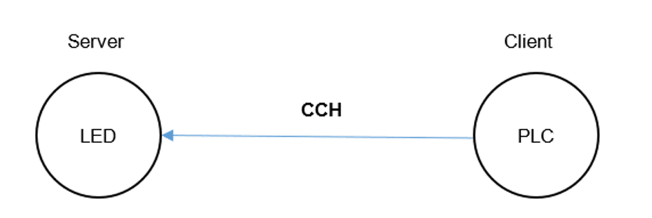
One channel over TCP/IP: the PLC acts as the client, the LED controller as the server, listening for requests and reacting per the protocol.
Pre-requisites
Both PLC and LED controller are connected via Ethernet and equipped with a stream-socket interface.
Full duplex
Once a connection is established, each peer can send and receive telegrams asynchronously.
Telegram counter
Both peers reset the counter on connection. The sender increments per transmission; the receiver processes only when the counter changes, else starts an Rx timeout.
Keep-alive
Each peer must receive at least one telegram within the RX timeout — a keep-alive telegram is sent at polling time to keep the connection healthy.
Error management
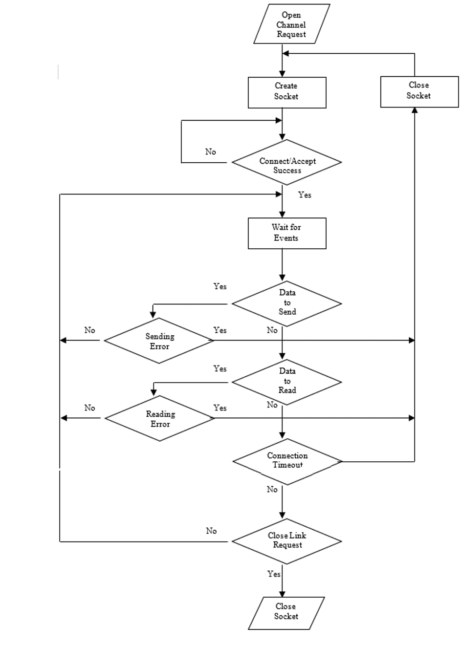
On a communication timeout or error, each peer closes the socket and attempts to establish a new one.
Byte order
Byte order and socket parameters are fixed in the interface document so both peers decode identically.
Connection management
Both communication nodes implement the connection-management flow shown here — from socket creation and listening through data exchange, timeout detection and reconnection.
The socket parameters (addresses, ports, timeouts and polling times) are fixed in the interface document:
Message structure
The channel transmits three message types, each with a header, a body and a tail. The header carries the progressive number, message ID and pixel length; the body carries pixel data where applicable.
| Channel | MSG ID | Type | Direction |
|---|---|---|---|
| CCH | 101 | KEEPALIVE | PLC → LED controller |
| CCH | 102 | PIXEL_DATA | PLC → LED controller |
| CCH | 102 | ACK | LED controller → PLC |
Each pixel is an unsigned double word of RGB intensity, values separated by a delimiter; the last pixel ends with an ETX character, which signals the host that pixel data is complete. The host then replies with an acknowledgment carrying the same header, with an empty body. Keep-alive and acknowledgment messages have fixed length; the pixel data message length depends on the pixel count — and the host polls until it encounters the ETX character.
KEEPALIVE
Keeps the connection up when no data is exchanged — identical structure on all channels.
Example:
Header <0x02><0x01><12514><101><0>
Tail <0><0><0x03>
ACK
The mirror of the received header and tail — on reception, each peer’s first action is to send it back.
Example:
Header <0x02><0x01><12514><101><5>
Tail <0><0><0x03>
PIXEL_DATA
Variable size — the pixel-length field indicates how many pixels to drive.
Four-pixel example:
Header <0x02><0x01><196531><102><5>
Data <0x7FEECCAA><0x7FEECCAA>
<0x7F44CDAF><0x7FBBA08A>
Tail <0><0><0x03>
Message exchange sequence
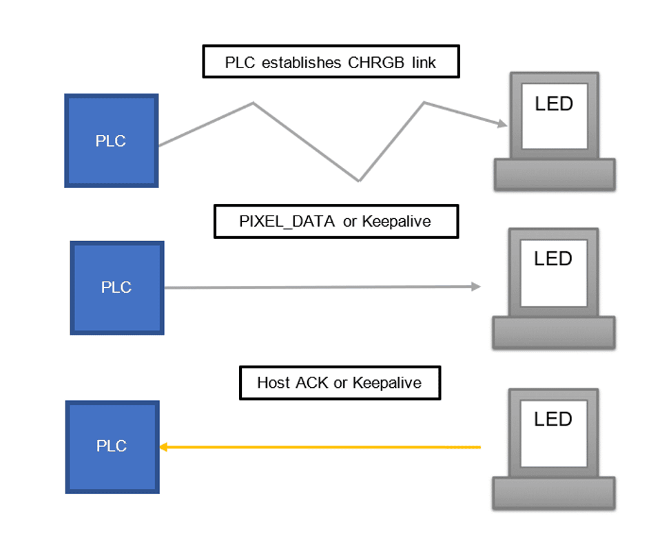
The client accounts for message losses from connection drops, buffering messages for re-send; the host keeps the latest LED state when correct data arrives and acknowledges each telegram — on ACK, the client sends the next string.
One practical note for LED applications: sending strings faster than 30 frames per second is pointless — the human eye can’t tell the difference — so string messages are sent at a fixed rate no faster than 30 fps.
Summary
This case presented an exciting, fun project: why custom interfaces are sometimes the right answer, and an easy one to implement. The approach generalises to any project — the same interface style can drive communication with barcode tunnel scanners, as explored in our Control Design for a Sorting System case study.
Need two machines to talk to each other?
Custom protocols, standard buses or anything in between — we’ll design the interface, write the document and build both ends. The first conversation is free.
Contact Us
You can find us at
Address
Lytchett House, 13 Freeland Park, Wareham Road
Poole
BH16 6FA
United Kingdom
Phone
+44 20 4570 2902
(Monday to Friday - 9 AM to 6 PM UTC)