
● CASE STUDY · AUTOMATION ENGINEERING
Control Design for a
Sorting System.
The full life span of a control project — from problem definition and performance requirements to electrical design, modular software architecture and state-machine implementation.
Purpose
The objective of this case study is to showcase our expertise with an example. It shows the life span of a simple project from solution definition to execution phase. Throughout the study, we will walk you through all phases, from problem definition to implementation.
Over the last years our engineers have led each of these phases on different occasions. In this study, we start with a proposed solution and a simple description, then act as the lead technical engineer defining and requiring information from the client — assuming some values to be able to proceed with the implementation.
Problem Description (from a client)
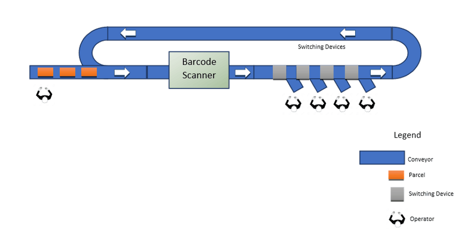
Consider a plant consisting of several conveyor belts, a barcode tunnel scanner, sorting devices with four destinations, and a turning loop — see the diagram.
This type of plant exists in e-commerce storage areas: the operator on the left picks orders from nearby shelves and places parcels on the infeed conveyor. The conveyor system transfers parcels through a dynamic barcode scanner, where the control system sends destination requests to a sorting computer. The sorting computer responds with a designated destination for each parcel, and the conveyor system transfers it to one of the four destinations on the right. Parcels with no destination return via the loop and the process repeats.
*This example shows only the basic functionality of the system and does not consider contingencies, to keep the case study relevant.
Solution Approach
When dealing with such a problem definition, it is important to start by requiring data about the system and checking whether the system can handle those requirements. Our responsibility is to make sure the system reaches the required performance and to guide the client through the design phase to prevent poor performance.
The first requirement is target performance — in such plants measured in parcels per hour. Note that one operator feeds the system while four people handle items at the destinations: this automatically triggers the need for a buffer system, since one operator cannot keep four destination operators busy. One suggestion is a long infeed conveyor where the operator can lay parcels back-to-back without gaps — followed by a gapper system, as the barcode tunnel scanner has constraints on the minimum gap between items.
The barcode tunnel constraints raise the next question: is there any local regulation limiting maximum conveyor velocity? Performance is a function of conveyor velocity and the front-to-front gap between items — if the gap is high, velocity must be high as well.
One last clarification is the scope of supply of the sorting computer. If it is in the client’s scope, we define an interface document to the control system: the medium of communication, message structure and messaging protocol (keepalive, message route, error handling, etc.). Once these requirements are defined, we can move on to the electrical and control requirements.
*To keep the case study short we do not consider material types, paint, conveyor heights, mechanical clashes or preferred OEM brands — we assume all those requirements are met.
Electrical / Control Requirements
The proposed system requires motors driven by VFDs (Variable Frequency Drives), photoelectric cells (PECs), power panels and electrical accessories. To give input to the electrical schematic design, we work through the checklist on the right.
In such systems we usually go with a decentralized control design: input/output signals connect to distributed VFDs, and the VFDs connect to the main control system through Profinet. Additional IOs are handled by distributed IO modules on the same network. Different field buses exist — based on requirements and budget, variations can be adopted. Profinet, for instance, allows fast remote diagnostics, which means lower downtime.
Our job is to provide a long-term, sustainable solution rather than focusing only on cost reduction — we guide clients through a cost/benefit analysis to find the best answer to the problem.
The design checklist
- Check required applicable norms (CE, UL, UKCE, …)
- Check Safety Integrity Level (SIL)
- Total number of motorized conveyor belts
- Total number of 24-volt IO devices (sensors, buttons, light indicators)
- Calculate power usage
- Determine the electrical interface with third-party systems (scanners, sort computer)
- Study each device's position to determine cable lengths
- Check network topology for field devices (ring, bus, …)
- Determine CPU type based on memory and performance requirements
- Define local/remote monitoring system
Control Design
With performance and electrical requirements defined, the focus turns to the design and implementation of the control logic. We start by listing the devices to control — see the list on the right.
From that list we conclude that we need 7 main function blocks, one routine per device type, called for each component with its own parameters: hardware address, length, speed set-point, current limit, and so on.
Devices to control
- Conveyor belts
- Variable Frequency Drives (VFD)
- Photoelectric cells
- Light indicators
- Destination chutes
- Switching devices
- Barcode tunnel scanner
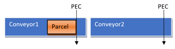
Each function block requires inputs/outputs and variables to store data used by other devices or for visualization. For each function block we define two data types: IO parameters data — the parameters that differentiate each item (a conveyor’s length, a VFD’s hardware address) — and IO logic interface data, used to send and receive data between devices. Two conveyors in series, for example, must exchange data to control the flow of parcels:
Each system component also has states and alarms to store and share with HMIs — some alarms prevent VFDs from running due to overheating, and every control device must be monitored to run the system safely and correctly.
Once each function block is defined, function calls are invoked per component. The architecture below shows the overall system. Following this modular approach keeps the architecture simple and maintainable: any change touches one function block, rollout is easy, and most callbacks can be auto-generated from a simple input file of system parameters — no specialist needed to generate the overall system software.
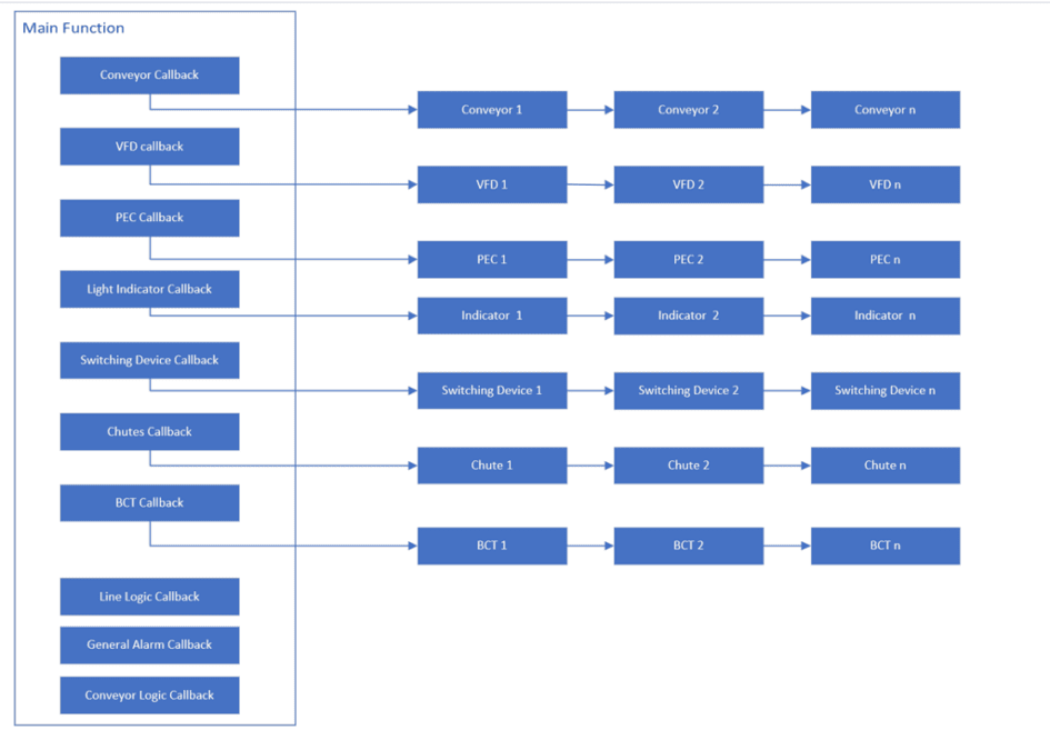
Note that the VFD function is deliberately not part of the conveyor belt block. Conveyors could be driven by different VFD brands, soft starters or relay logic — keeping the design invariant to the drive type. If three conveyors run on VFDs and two on 24-volt drives, the conveyor callback stays identical; only a new drive function block is added. This is what makes the architecture easy to maintain.
State Machine Example: Vertical Sort Unit (VSU)
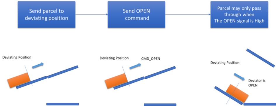
This example showcases design using the state-machine approach. A Vertical Sort Unit diverts the flow of parcels into different paths: it consists of two conveyor belts with two configurations — closed or open. Closed, parcels flow to one path; open, they flow to another.
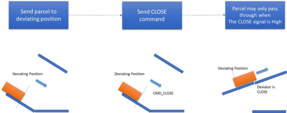
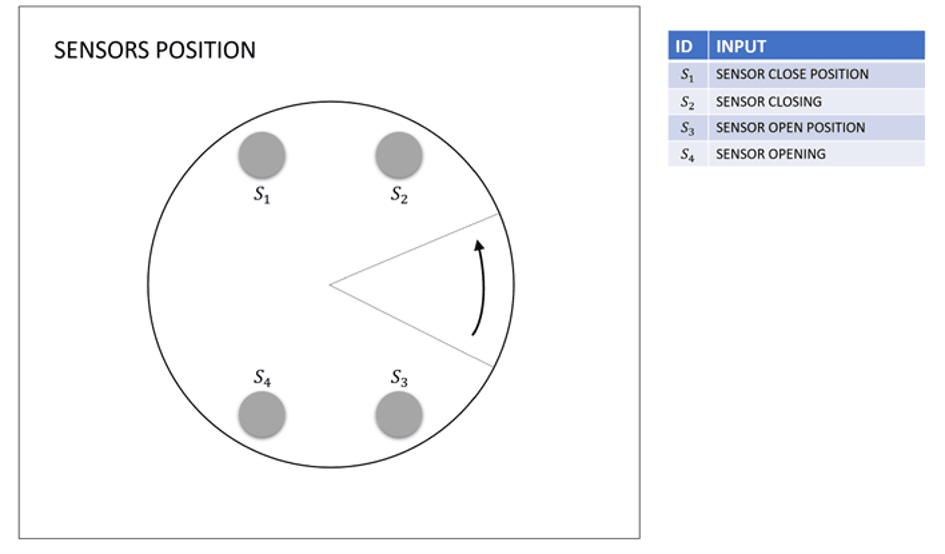
The VSU is equipped with four proximity sensors: two trigger the slowing command, and two indicate the closed or open position.
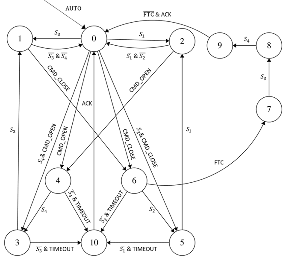
The VSU has two operation modes. In automatic mode, it changes state as parcels enter the system — the main control unit sends open or close commands to divert flow, while the VSU monitors for jams that might block movement and handles them automatically. In manual mode, the operator issues jog commands and verifies there is no obstacle — used for maintenance or contingencies only.
Automatic Mode
To design a state machine we need a list of states and events. The diagram shows the automatic-mode states, the events that trigger transitions, and the jam-handling paths.
Manual Mode
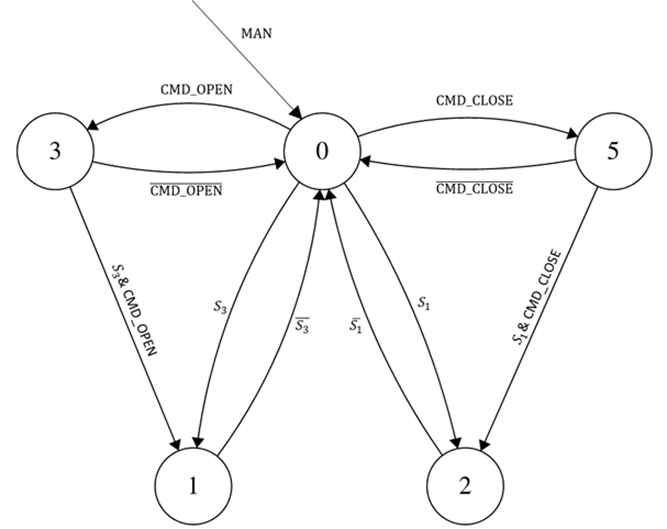
The same method applies to manual mode: a defined list of states and events, expressed as a state machine. Documented this way, the functionality is easy to communicate across mechanical, electrical and software teams.
Summary
This case study presented a method of work for solving a control problem in a simple sorting system: a system description with limited requirements, a methodology of asking the right performance questions and suggesting improvements — standard practice at the start of any project.
It listed the requirements to identify before electrical design, showed an approach to designing a maintainable software architecture with the data types stored per function block, and demonstrated how to design a software component using a state-machine approach — easy to document and to communicate across teams.
We hope this case study explains the methodology and mindset we bring to technical problems.
Want this methodology on your sorting system?
From problem definition to commissioned control system — tell us about your line and we’ll walk you through the same process, starting with a free consultation.
Contact Us
You can find us at
Address
Lytchett House, 13 Freeland Park, Wareham Road
Poole
BH16 6FA
United Kingdom
Phone
+44 20 4570 2902
(Monday to Friday - 9 AM to 6 PM UTC)